

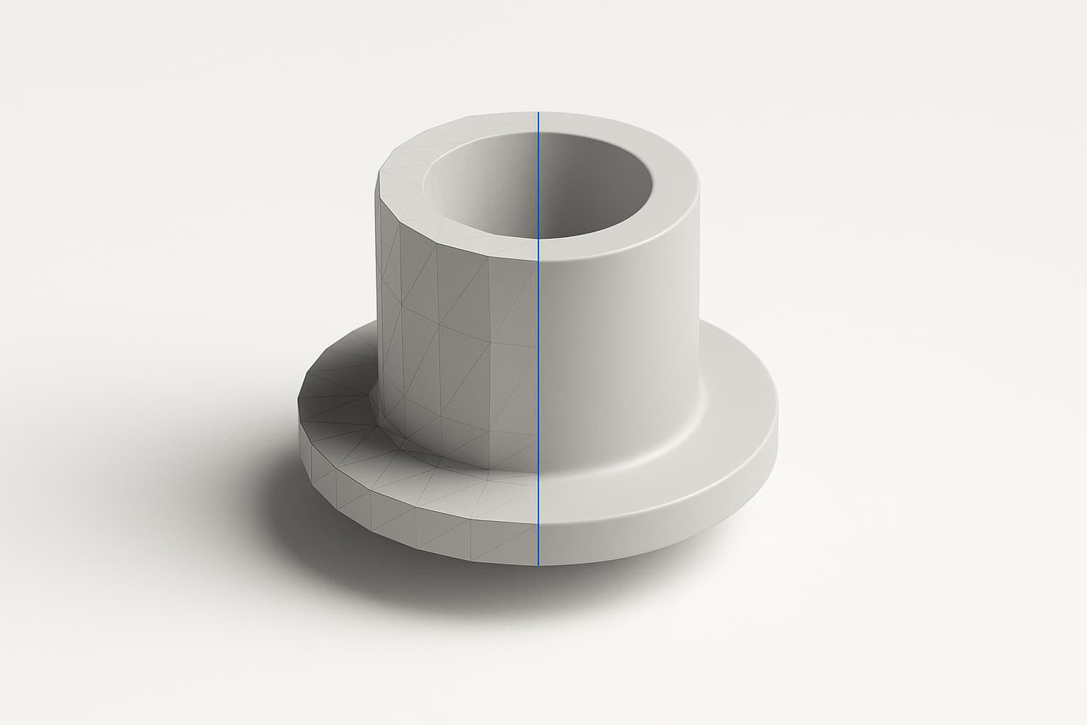
STEP has landed in Zenve3D, in both directions. The export sheet is a format picker now — STL, as before, and STEP — and a STEP file can come in too, arriving as a solid you build around. An STL is what your slicer wants; a STEP file is what every other CAD program wants — and the difference is bigger than a file extension.
Mesh versus solid
An STL is a mesh: your part approximated by triangles at some tolerance. It's exactly right for printing, and exactly wrong for everything else. Open an STL in another CAD app and a cylinder is no longer a cylinder — it's a few hundred flat facets pretending. You can't put a precise hole through it, can't measure it exactly, can't edit it as the thing it was.
A STEP file carries the exact geometry — the true cylinders, planes and fillets your recipe produced. That's also why the export sheet shows no Quality section when STEP is selected: there is no tolerance to choose, because nothing is being approximated. The section is absent rather than greyed out, on purpose — a setting that can't apply shouldn't sit there looking adjustable.
One file, many bodies
STEP can hold several solids in one file, which STL structurally cannot. So the export picker takes a body selection, and "the box and the lid, one file, two solids" is a thing you can actually ask for — one attachment to send, arriving as two editable parts on the other end.
Verified round trips
Interop claims are cheap, so here's what was actually checked: files exported from Zenve3D open and edit in Fusion 360 and FreeCAD on a Mac, and a file exported on the iPad opens in Shapr3D on the same iPad. Solids, not meshes — you can keep modeling where the file lands.
If you drive the zenve3d CLI, the format is a flag and --body scopes whichever exports you ask for, so two files from one run can't disagree about which body they mean.
Import: build around real geometry
The other direction is the one that changes how you design. Import a vendor's STEP model — an Arduino board, a motor, a bearing — and it lands in your project as a solid, at its real dimensions. Instead of modeling an enclosure against a datasheet drawing and hoping, you design around the actual part: position it, sketch relative to it, and see the clearances on screen before anything is printed.
This was the founding use case for the whole STEP effort — start an enclosure on the iPad, drop the board in, and know the standoffs line up because you can see them, not because you measured a PDF twice.
Why this matters for a maker tool
Nobody's whole workshop lives in one app. You model an enclosure here, a collaborator refines it in Fusion; a machine shop asks for "a STEP, not a mesh"; a part you designed this year should still be exact geometry in five, whatever app you're running then.
STEP is how a part stops being locked to the tool that made it. For an app built around the idea that your model is a recipe you can always re-edit, exporting a dead mesh as the only way out was a real gap. Now the geometry leaves the same way it lives inside the engine: exact.
Your parts shouldn't be hostages of the app that made them.
Honest limits
One small iPad quirk: with no CAD app installed, an exported STEP may show as a blank document icon in Files. The file is fine; iOS just doesn't know how to draw it.
What's next
With geometry flowing both ways, the current milestone's remaining piece is rigid mates between parts — seating a lid or a board so the fit is checked on screen, not eyeballed. The same push also shipped feature patterns — that post is here.